Saturday, February 28, 2015

Old Dog, New Trick

Now that Robie's bumper sensor is wired up, I felt I should add some code to make it functional. For the most part the control logic is the same. But now when the bump sensor activates I stop the motors from going forward until they have gone in reverse first. This prevents the wheels from spinning constantly as Robie is inevitably steered in to a wall or some other inanimate object. Additionally his eyes will turn purple. Why? Because why not. Also you ask too many questions :-P

Here's how this looks in action:


It's a bit dicey without the cover on. Unfortunately the cover is part of what holds the bumper in place. So it pops off quite easily. But I managed to at least take that video.

Here's a diff for the additional code:

https://github.com/meatheadmike/robie_motor_control/commit/9e3fbd31e4923b0f36f065001d1aed07679bfb31

As you can see there's not really much to it. I set up the pins for the bumper and the other switches (which don't really do anything yet). Then I set up 2 global variables to specify when the bumper is tripped. Why two? Because I want to ensure both motors are stopped individually. That way I know both have gone in reverse so I can reactivate the forward motion.

The main work is done in the bumper_pressed_callback function. The callback is triggered by an interrupt. So the code will continue looping until the bumper is pressed. Then the callback gets triggered and does its magic.

Thursday, February 26, 2015

Then and Now

I don't really have much to say today. I didn't get any time to work on Robie yesterday. So perhaps I'll take the time to pause and marvel at modern technology.


On the left is Robie's original control board. On the right is a Raspberry Pi model B+. Robie's new control board is a model A+, so it's even smaller than this.

Though Robie was pretty cool for his time, he certainly didn't have much computing horsepower. It's amazing what 28 years of technological advancement brings. Cell phones were the size of a brick and cost as much as a car when Robie was first introduced. The World Wide Web didn't exist yet (never mind Facebook, Twitter and selfies).  And a desktop computer was thick, beige and literally took up your entire desk.

Now we have a Raspberry Pi that costs < $50 and can run circles around that same beige box. I mean that literally because Robie has wheels of course :-P

Wednesday, February 25, 2015

Staying Grounded


That little mess of wires there on the bottom part of the image is what I'm referring to as the positive and negative buses. A build such as this has numerous peripherals (switches, sensors, etc). And each one of those needs either a ground connection or a positive and ground connection. So this was my solution. I created a bus out of a chip socket. I soldered all the pins together on one side. Then I could plug in my wires on the other side. This makes for easy prototyping. It also makes for easy disassembly (vs soldering directly).

Well that was working fine until yesterday when I was trying to hook up Robie's arm switches. I started by removing all the ground and positive connections. When I plugged everything back in and booted him back up, I noticed the LED "eyes" were extremely dim and flickering. Hmm. I checked all of the connections. Everything was plugged in to the correct spot. So then I pulled the ground for the LED and plugged it in to a different slot on the bus. Bingo! Now the LED's were working again.

So basically my soldering job on the ground bus wasn't as great as it should have been. Either that or the pin wasn't making great contact.  Whatever the reason, I decided to change how the power distribution worked.


The image above is the end result. Basically I took a bunch of prototyping wires, hacked the ends off and soldered them all together. Now I have the same flexibility of being able to remove and reattach components, but with a (hopefully) better soldering job. Actually I know it's a better soldering job!

So this experience got me thinking... Maybe the reboot & WiFi dropouts I experienced earlier weren't due to lack of power but instead a grounding issue like the LED's. It was easy to check this... I simply disconnected the power pins from the voltage converter and plugged it in to the power buses.

Nope. No luck. Same issues. Sigh. Well at least that's confirmed now.

Monday, February 23, 2015

Readin' and Writin'

So one of the things that I find continually happening as I'm experimenting with the Pi model A is that I'm locked out when the WiFi doesn't connect. This happens for various different reasons. A config change being the most common culprit. Since there's only one USB port and no Ethernet that doesn't leave me with a lot of options to log in and see what's going on.


Typically when it's a desktop scenario you can connect a PL2303 to the Pi's UART and see what's going that way. But that doesn't really work in my situation since it's tough to access the pins unless I pull the covers off of Robie.

So invariably I end up yanking the power, pulling the micro SD card and then plugging it in to my model B.

The problem here is 2-fold. A) I can't see any of the logs or what caused my glitch and B) I run the risk of corrupting my disk image every time I yank the power without shutting down correctly.

The second issue I think I've solved now. Basically I've set up the Pi to be read-only except for when I run a special script. This way I can yank the power to my heart's content but nothing will be damaged on the SD card.

I primarily followed the steps here:

http://blog.pi3g.com/2014/04/make-raspbian-system-read-only/

The only thing I have to add is that the boot and root partitions were not /dev/mmcblk0p1 and /dev/mmcblk0p2 like they mention in the post. I imagine this is because I'm running a more recent build of Raspian. Who. knows. It was a minor tweak.

So the other issue with logging in and seeing what's causing problems I'm going to try and solve with one of these:


It's called a Bluetooth ttl module (or sometimes a Bluetooth slave module). Basically it should allow me to have Bluetooth connectivity on my Pi without consuming a USB port.

I also hope to provide a way to set the WiFi parameters via the Android app using this Bluetooth module.

Whether or not I succeed or fail will be covered in another post...

Friday, February 20, 2015

And Now For Something Completely Different

Alright. My Android code is cleaned up enough to share with the masses. So here's the github link:

https://github.com/meatheadmike/robie_rover_android

Please don't judge me too harshly. This is literally my first ever Android project. So there's lots that could/should be improved/revised.

Here's what it looks like once compiled and installed on my Cyanogenmod 12 Lollipop-toting Samsung Galaxy S5:


As you can see the real-time video feed is in the center of the screen. This code was mostly pilfered from the simplemjpegview project. No sense in reinventing the wheel, right? The code I worked on was the control code.

The text in the upper left-hand corner of the screen shows the value we're sending to each of the motors. It will be in the range of -100 to 100 for either side and is interpreted as a duty cycle percentage to send to the Pi.

The navigation communication happens over UDP. Because it's UDP it's got less latency than TCP. We don't have to wait for acknowledgements or anything like that. But it's also less reliable. That's ok for motor speed control because we're flooding the Pi with speed data. If one or two packets don't make it through nobody will notice. You'll note though that when the app pauses or exits I make sure to send 3 stop requests to the Pi (see the RoverLoop/run function here). It would really suck if Robie kept moving when the app shut down! I suppose this still could happen in a force-close or system reboot situation though.

There are currently 2 buttons on the main interface. The spin button on the right currently does nothing. But I'll eventually make it so that it can spin in place (i.e. the left and right wheels move in opposite directions). The rove button basically turns on and off the motors. We default to off so that Robie doesn't immediately spring to life the second the app opens. That could be a bit awkward.

There are probably a few things I'll like to add in the future. First off will be that spin button that I mentioned. But I'd also like to have a mode selector. Since I'm going to have one on Robie as well, this means that I'll need some way of sending data from Robie to the phone so they can sync up. This either means I need to set up a UDP server on the phone or switch to TCP for the communications. Either approach has pluses and minuses. So I'll have to mull it over a bit before I move down that path. For now I have a functional bot.

Wednesday, February 18, 2015

Next Steps

So at this point I have something that works for demo purposes. I'm still waiting on a few parts before I can bolt Robie together and focus purely on software. On the hardware side of things I have the following items on my do-list:


  • Secure the Pi to the chassis in a better fashion. Right now there's a single screw and spacer holding the board to the chassis. Not ideal. I have some nylon screws and spacers on order which should make the mount rock-solid.
  • Solder and secure the LiPo charging board. It has to arrive in the mail first of course. Until then I'm stuck with USB tethers.
  • Mount and wire up the audio amplifier board. It also has yet to arrive. This will give Robie some vocal capabilities. What he'll eventually say or sound like I'm not quite sure yet.
  • Connect Robie's switches. The most important of these being his top switch. I intend on this being a mode switch.
  • Connect the ultrasonic ping sensor. It's mounted of course, but I have yet to connect it to the Pi.
  • Figure out what to do with the Ir distance sensor. My hope is to mount it somewhere near the center of the front bumper and point it towards the floor. That way Robie will know in advance when there is a set of stairs approaching and take the appropriate action.

To that end I mapped out the GPIO wiring. I found a nifty printable chart online using my Google-fu. Honestly I think it was from the main raspberrypi.org site, but I can't recall:


So now I can have some confidence that every peripheral is accounted for.

Software-wise my main priority is going to be shoring up the Android code and then releasing it on Github. My estimation in this is probably some time over the weekend.

Tuesday, February 17, 2015

Finally some code!

I finally got around to uploading my motor control code to Github:

https://github.com/meatheadmike/robie_motor_control

I'll be making updates to the code as time goes on. I'd like the ability turn the motors on and off from a specially crafted packet. And eventually I want different "modes". So mode 1 is control via the gyros on the phone like I have now, but perhaps mode 2 will be bump-n-go mode (much like the original Robie).

Anyways, as this is a functional "release" I've tagged it as v0.1. Enjoy. Or don't. You get what you pay for, and this is free :-P

Monday, February 16, 2015

It's ALIVE!!!

So I managed to get my Android code flushed out to the point where I have streaming video and tilt controls. Robie is tethered by 2 USB power cords at the moment. This is due to the unfortunate discovery that a single power source at 2 amps doesn't supply enough juice. But I didn't let that stop me from testing out my code:


The video is not the greatest. I had to film from my old iPhone 4 as the control code is running on an Android device. But as you can plainly see the controls work nicely! I can move forward, backwards and steer left and right.

I even added some lighting effects to the mix. When the left or right wheel moves the corresponding eye will light up. Green is forward, red is reverse and blue is stationary.

Some learnings from my testing:

1. 3 ft usb extensions are certainly not enough
2. The "spin" code I talked about in the last post really doesn't work too well in practice. It's too jerky.
3. There were several tweaks to the rotation angles as I discovered what felt most natural.
4. Real time streaming is really hypnotizing!
5. One of Robie's motors is pretty noisy. I think it's probably on it's last legs.

I'll post the motor control code soon (Probably tomorrow?). I'm just not at my laptop at the moment. But it's in a good state to share. The Android code needs a bunch of work to make it presentable.

If only my LiPo module would arrive in the mail I could do away with the tether for good! Soon enough. I guess patience is a something something.

Sunday, February 15, 2015

Command And Control

So first a followup: The answer to the issue I was facing with the WiFi dropping out did indeed turn out to be power related. Unfortunately I don't have an ammeter. This would be hugely beneficial at the moment. But through some trial and error I discovered that the dc-dc step up module was sucking too much juice. This meant the Pi and the WiFi dongle were starved for power. I'm actually surprised it didn't completely shut down on me. So it seems that for now I'll need to run the step up module & the motors on their own power source. I tried running the motors off of 5v and it was pretty sad how slow it ran :( Let's hope that LiPo charging board gets here soon!

Alright... On to more pressing matters. I've been mired in Android (Java) code for the past couple of days. I want to be able to control Robie by tilting my phone forward, back, left and right. It turns out this is a bit more complicated than I had initially envisioned.

I'm using the orientation sensor in the Android SDK. It says it's deprecated, but it still works in Lollipop. There are ways to work around the deprecated feature, but I'm fairly new to Android so I went with the simpler option. Use it till I lose it, right?

Orientation gives you angles of rotation. So if I have my phone flat relative to the earth I get 0 degrees of rotation for both the Z and Y axis (the ones I care about). If you tilt forward, you'll get negative numbers out of the Z axis. Tilting backwards will get you positive numbers. If you tilt left you'll get positive numbers out of the Y axis and naturally right will get you negative numbers.

So the first thing that I found was that you don't want to just map rotation numbers directly to the PWM duty cycle of the motor control. If you did, you'd have to tilt your phone 90 degrees so that the phone's screen is completely facing away from you to go full speed forward. And by extension, you don't really want the starting point to be at 0 degrees for your forward/back control. That's not a natural way to hold the phone. You probably hold your phone at something closer to -25 degrees. What's needed is a way to specify bounds. So that if you tilt your phone beyond a certain point it's not going to go any faster.


So before going further I decided to sketch out an idea of how I wanted the control mechanism to work. I came up with the drawing you see above. The thinking was that you don't want Robie moving around if your hands are at rest. So I'd include a "buffer" zone where rotation values would be ignored and simply output as 0 movement.

Then I thought wouldn't it be cool if Robie could spin in place if he's not going forward or backwards? If you're going forward and to the left for example, both wheels are moving forward but the right wheel is going to move faster than the left wheel.  If you are spinning in place then both wheels are moving at the same speed but in opposite directions.

I'm not totally convinced this will play out perfectly in practice though. Because if you're tilting back to slow down and then you cross the buffer zone all of a sudden Robie is going to suddenly start spinning. I think this might be too jarring. I don't know. I'll have to test it out to find out for sure!


Here's a teaser shot of some of the Java code. I'd share the rest but it's a horrible mess at the moment :( I promise to put up a Github link once all the basics are sorted out and she actually functions.

Thursday, February 12, 2015

The Saga of Streaming Video

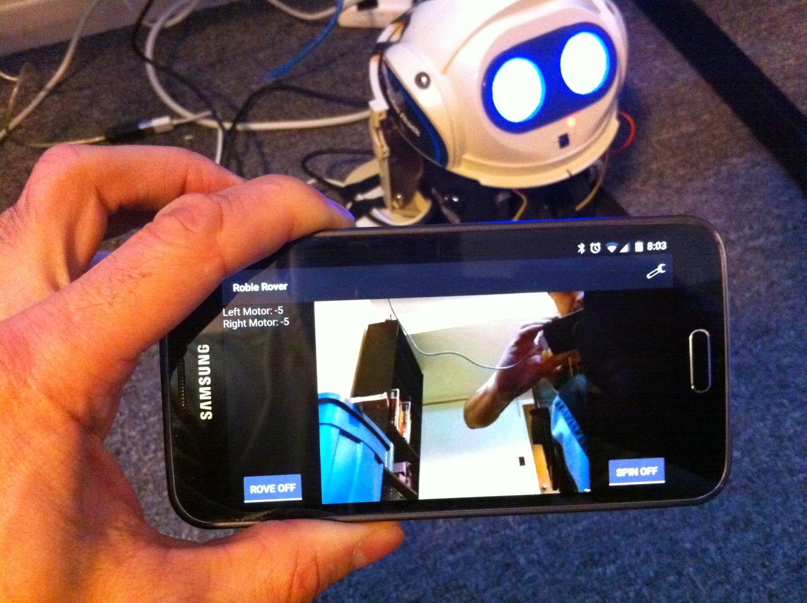
So I set out to play with streaming some video over WiFi. The eventual goal is to have a control interface on my Android phone. The tilting action from the phone will cause Robie to move forward. back, left and right. And of course the mobile screen will show whatever Robie is looking at through the Raspi cam that's now secured to his skull.

There are a ton of different options for streaming video from the Pi. Ideally I thought at first that I'd use the built in h264 encoder and then fire off a compressed stream to my destination. Ideally this stream would be done using UDP transport so that we could avoid re-transmission of packets. All modern phones have h264 decoders in them as far as I know. So this should be pretty easy, right?

Well my experiments didn't turn out so well. I was able to get h264 streaming working over TCP transport. But the latency was unacceptable for a real time application such as this. You would wave your hand in front of the camera and then 5 seconds later you'd see it in the video. I tried several different approaches, encoding with vlc, encoding with ffmpeg and encoding with gstreamer. I tried various different resolutions as well. All to no avail. Either the stream had too much latency or the stream simply wouldn't play.

Eventually (though the magic of Google) I came to realize that mjpeg (motion jpeg) streaming was the best approach to use. Intuitively you'd think h264 with hardware encoding would be the way to go. But you'd be wrong.

So there were 2 different mjpeg streamers that I managed to get working nicely:

mjpeg streamer: http://sourceforge.net/projects/mjpg-streamer/
which has a nice tutorial here:
http://wolfpaulus.com/jounal/embedded/raspberrypi_webcam/

and

uv4l: http://www.linux-projects.org/modules/sections/index.php?op=viewarticle&artid=14

Of the two approaches I found uv4l better. It seemed to have less CPU utilization and the embedded web application has a nifty configuration screen where you can adjust camera parameters on-the-fly.

Now my latency is almost imperceptible. I can wave my hand in front of the cam and see it on the client end instantaneously. One item of note though, I did have to lower my resolution and framerate considerably. 640x480@15fps seemed to be the lower limit of realtime streaming. I opted for lowering it even further to 320x240@15fps. This way I should have less issues with bandwidth and more CPU for other tasks.

One last item to share... My tests were running flawlessly on my Raspi B+. But when I cobbled everything together in my A+, I ran in to an issue. When streaming video the Pi works nicely for all of 10-30 seconds. Then inexplicably the ping times slow to a crawl and the video gets super choppy - eventually stalling out. It's so bad that sometimes I can even log in through ssh.

I thought I might have a driver issue with the WiFi dongle. After playing with several settings and getting nowhere I thought I'd try putting it back in the B+. Now she streams flawlessly again. So I can think of 2 possibilities here:

a) The A+ has 1/2 the memory of the B+, so it may be running in to a RAM issue.
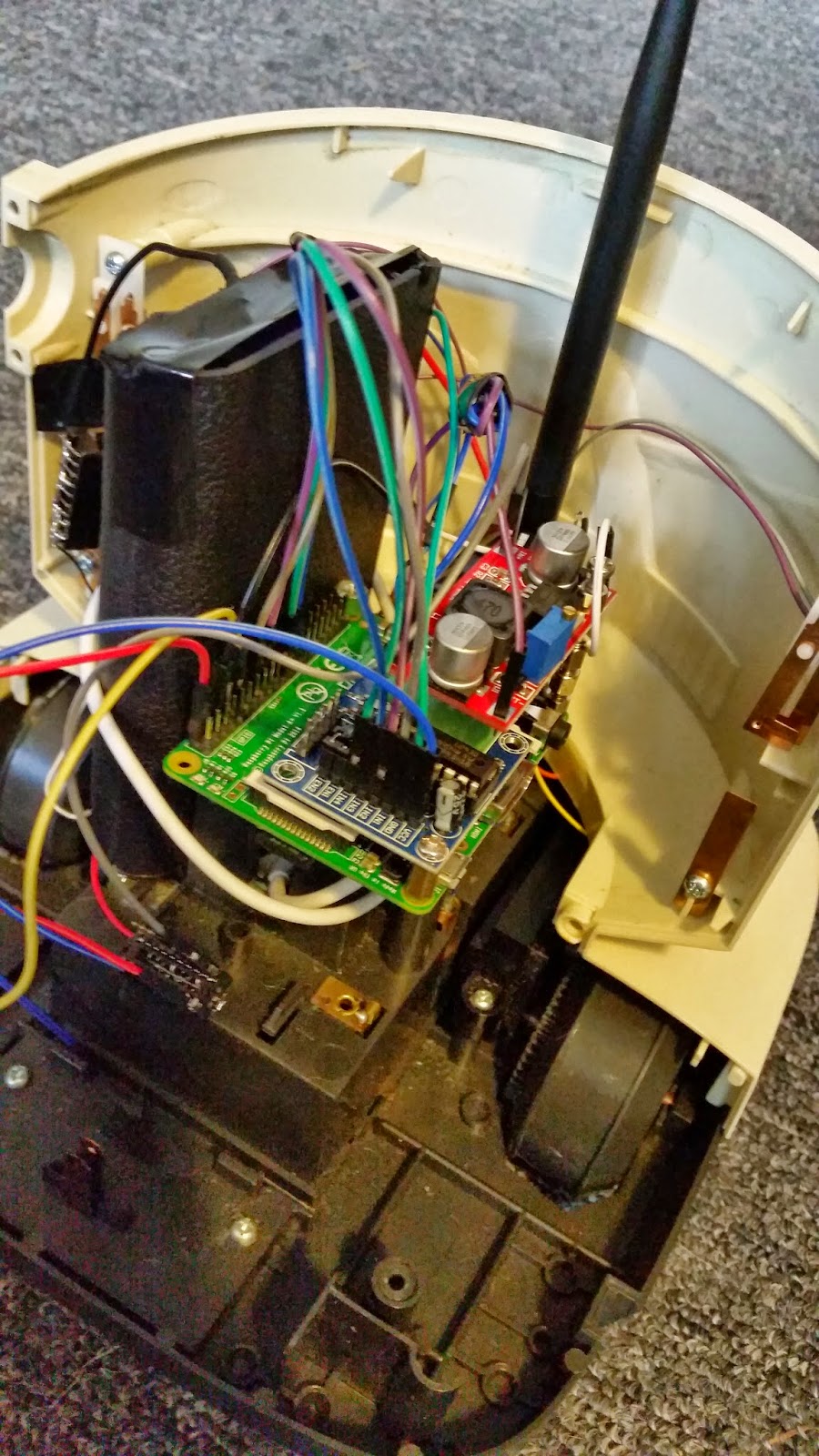
b) The A+ has the motor controller, DC-DC step up board and the ws2812 modules all pulling power from the same source. The B+ experiment was *only* using the raspicam and the WiFi adapter. So it could be a power starvation issue.

Of the 2 options, b) stands out to me as the first thing to test. Perhaps tonight I'll see where that leads...

Tuesday, February 10, 2015

The Eyes Have It

So I decided to play around a bit with the NeoPixel Jewels (ie Robie's new "eyes"). The first thought I had was that it would be nice to have a visual indication of when Robie is done booting up. This is what I came up with:


The video quality is not the best. It looks a lot slicker in real life! I think it adds a certain something to Robie's personality.

It's a pretty simple python script. For anyone who is interested, I put the code up on github:

https://github.com/meatheadmike/robie_boot_anim

Monday, February 9, 2015

A Day For Hardware

There were a few hardware items on Robie that I decided to tackle yesterday. One of the more annoying things that I've had to deal with since day 1 is the fact that my old used-and-abused Robie didn't have any rubber tread left on his wheels. This makes traction a tricky proposition. I was able to conduct some tests on the carpet ok, but he still slips a bit.

I happened to have some robot wheels kicking around from another project. These are the typical mounted-on-yellow-plastic set that you see in 90% of the robot platforms for sale in Ebay. They looked like they might fit the bill without modifications, but upon closer inspection both the diameter and width were too big.


That didn't deter me much though. I carefully cut down each of the side to make the track thinner. Then I cut out a section to shrink down the diameter. A bit of contact cement secured them to the original Robie wheels. Now they look like they came from the factory! There's a small seam if you look closely, but other than that it's pretty clean.

Next I went on to try and mount my HC-SR04 distance sensor. The best sport I could come up with is the front panel where the speaker mounts. As it turns out, there is enough room in there for both the distance sensor and the speaker (which I intend to utilize).


The only trick to cutting the plastic to to use a small cutoff wheel on the Dremel and go slow! My measurements were bang on, so the sensor is essentially press-fit in place. I put some electrical tape on it as well (not shown) just for insurance.

Finally I tackled the camera mounting. This part was a bit tricky. Because the ribbon cable for the Raspi cam is fairly short, I needed to ensure that the ribbon socket was pointing down. The circuit board barely fits between the eye mounts and the bottom lip of the head. So I was careful about where I drilled my hole. The Raspi cam lense enclosure itself is square. So after I drilled a pilot hole I had to file down the hole to make it square as well. After I got the fit right I secured it using some 2-part epoxy. I was careful to only use a couple of small dabs on the sides. Therefore if I ever need to replace the cam, all I need to do is cut the epoxy with and exacto blade.


He kinda looks like he has a mustache now, doesn't he?

Sunday, February 8, 2015

Piecing Frankenstein Together

So this is basically my test fit for the hardware:


It was a tough squeeze getting everything in there. The Robie chassis, while spacious is a bit awkwardly shaped. You have to keep wires clear of the moving parts like the wheels and switches. And the head imposes height restrictions.


If you look closely you'll note that the power bank has been shaved down in height. This is because it wouldn't fit vertically otherwise. Basically I pried open the case and separated the batteries and logic board (ie that part I fried the other day). I used a Dremel to saw off the top of the case that contained the logic board. This shortened it significantly while still allowing me to use it as a protective casing for the batteries. Before I snapped the case back together I drilled some holes on one side and secured it to the chassis with screws and nuts.

The Raspberry Pi is secured to the chassis with only a single screw at the moment. You'll note though that the mounting holes overhang the battery compartment with a space in between them. So I will secure this a bit better with some spacers. I just don't have them yet. Thanks to the magic of Ebay they are on order though!

The motor controller and DC-DC step up modules are also mounted with only a single screw. This is also not such a great situation for ruggedness. At the moment I think my best option is to use some double-sided tape in addition to the screw. This should keep everything in place a bit better.

So you may be wondering what the DC-DC step up module is all about. My thought process on that one is basically the original Robie ran off of 6 volts from the battery. USB power will give me 5 volts. Robie isn't exactly fast at the best of times, so I wanted to make sure I was supplying enough current to wheels. The step up module allows me to dial in the voltage with a screw driver. Unfortunately there are no identifying markers on the motors. So I really have no idea what the specs are. So I set the voltage at 6.25 (assuming they built in a bit of wiggle room at the factory).

So far I haven't managed to burn out the motors and he seems to move around ok!

Saturday, February 7, 2015

Off With His Head!

Separating Robie's head from his body was a lot easier than I anticipated. If I remember correctly there were 4 screws holding the back section to the front. No guillotine was required. The existing LED's, ultrasonic mic's and push button were all attached with jst-type connectors.


My plan was to replace Robie's eyes with ws2812 programable LED's. Adafruit's NeoPixel Jewel 7's fit the bill nicely. Basically it's 7 ws2812's laid out on a circular PCB. The ws2812's are controllable from the Raspi using Jeremy Garff's excellent library. So all I have to do is write some simple Python statements and I can make the LED's do my bidding.


Soldering and mounting of the LED's went better than I expected. It actually looks quite professional (if you ask me). NeoPixel modules are daisy-chained together. So there are only 3 wires leading in to the eyes (+5v, GND and GPIO in). I had to do away with the red lense (otherwise I would be limited to a red color like the original Robie). But I quite like the look of the clear eyes. The NeoPixel modules were epoxied in place and left to dry over night. 


Here's a shot of the eyes fully assembled and connected up to the Raspberry Pi. The camera work strategically omits the massive pile of electronic parts sitting just out of sight ;-) Each of the 14 individual Neo Pixels is now individually controllable!

Friday, February 6, 2015

Part Of Me Wants More Parts

It's an amazing time we live in. Electronics experimentation has never been more accessible or more affordable. And the stuff you can build with off-the-shelf parts is pretty impressive. I thought I'd share some of the parts that are going in to this build. In the coming posts I'll explain why I chose these parts and how they will interface with the build.


List of parts and prices (inc shipping, USD):

- Powerbank (LiPo batteries): $21.00
- HC-SR04 ultrasonic distance sensor: $1.11
- L293D motor driver: $2.45
- M-F jumper wire: $1.28
- F-F jumper wire: $1.58
- M-M jumper wire: $1.58
-300mbps n/b/g USB wifi: $5.25
- IR distance sensor: $2.99
- LM2577S DC-DC boost module: $2.78
- LM386 audio amp: $1.11
- LiPo boost plate: $7.95
- Robie the robot (broken): $23.64
- Raspberry Pi A+, B+, 2x8GB microSD, raspi cam: $106.73
- 2x NeoPixel Jewel 7 LED's - $15.97

For a total BOM of: $195.42... So far ;-)

Most of what you see was purchased on E-Bay from various vendors in China. It takes up to a month and a half for the packages to show up. So it can be a bit frustrating. But for the patient the reward is cheap gear!

The Neo Pixels were purchased closer to home from maker-friendly outfit Adafruit.

The Raspi gear itself was obtained through Allied.

Thursday, February 5, 2015

MOAR POW3RZ!!!

Obviously a roving robot is going to be somewhat constrained if it has to be tethered to its power source. So I began looking at some options for battery power.

The Robie chassis has a battery door which accepts 4 D-cells. So that's an obvious first choice. And indeed that's a valid choice. Although the Pi and most of the peripherals run on 5v and 4x 1.5v D cells = 6v, it's possible to use a buck converter to get 5v. But that means running out and buying pricey D cells every time I'm out of juice. And from what I hear Pi's can go through batteries quite quickly.

So my other option was to use some sort of rechargeable source. There are many types of rechargeable batteries. And indeed I could have used D-cell ni-cads if I wanted to. But nothing beats LiPo / LiOn for bang-for-the-buck. That's what's in your power hungry cell phone and your laptop.

LiPo cells can have tricky charging requirements. Charge them too much or let them drain too much and you can damage the cells - or worse - set fire to your house :( I thought I'd do away with these concerns by buying something prepackaged that already had a proper charging circuit embedded.


So this is what I ended up with. It's a USB power bank. It's intended for charging up your cell phone or your ipad on the go. But lucky me the Raspberry Pi also runs off of the exact same 5v USB source. This one is especially nice because it supplies 2 amps on one port and 1 amp on the other. So if I find myself starved for power I can split off the drain across the 2 ports. The stated capacity is 50000 Mah. That rating is pretty laughable. It's probably closer to 10000 Mah. But even at that it should provide plenty of roving juice.

Of course the power bank wouldn't fit inside the chassis without a few modifications (which is why you see the 18650 cells and the charging board separated from the case in that photo). Additionally I ran in to an issue where the board cuts power to the USB ports. So the "on" button needs to be accessible.

My solution was to put the charging board in the battery compartment so that one simply needs to open the door and plug the micro USB cable in to charge her up. If the USB power cuts out, just open the door and press the button. Simple. Elegant.

Unfortunately somewhere in the process I seem to have nuked the charging board. Sigh. So I've gone ahead and ordered a new one on Ebay. For anyone facing a similar problem, the thing to search for is called a "LiPo Boost Plate".

The life of a hacker is never dull...

Wednesday, February 4, 2015

A slice of Pi

So in deciding to build a custom Robot in the Robie shell, another decision needs to be made. What to base the platform on? Two of the more common & popular choices are Arduino and Raspberry Pi. The both have their pluses and minuses. The biggest difference is that Raspberry Pi is essentially a full computer. It runs an OS and can be hooked up to a keyboard & monitor just like a desktop. The Arduino is more like a programmable piece of hardware. It seems to be better for single-task sorts of things that require precise measurements or timing. Or for extremely low power consumption applications. Either are valid choices for a robot build. I chose a PI because a) I already had one and was familiar with it's workings and b) The possibilities of hooking up a camera, Ethernet and speakers et al. seemed a lot more straight forward than with Arduino. And another bonus is that I could code in Python which I am already familiar with.


In choosing a Raspberry Pi there are actually even further choices to be made... Which model? The model A, A+, B, B+ and now apparently the model 2 B! I actually chose 2 different models for my purposes. The A+ and the B+. The 2 B didn't exist when I bought the project parts. But I probably still wouldn't have ordered it. It uses more power than the B+ and A+ models. As do the older A and B models. The B+ and A+ models strike a nice balance between performance and power. 

So why the B+ and the A+? Well I intend on running the robot off of the A+ exclusively. But For development I'd like to have the flexibility of more USB ports. The A+ also doesn't have any Ethernet or WiFi. So that makes it a bit more challenging to set up. Once configured I can easily remove the micro SD card from the B+ and stick it in the A+. And also who doesn't want more Pi's kicking around their workshop?

Tuesday, February 3, 2015

A Man And His Robot

When I was a child I received a memorable gift. It was a toy robot called a Robie Jr. from Radio Shack. Robie was pretty cool. He had an autonomous bump-n-go mode that allowed him to rove around the house. When he hit something with his front bumper he'd say "Excuse me" and turn in a different direction. But perhaps his coolest feature was that he could follow you around. Robie's remote control had an ultrasonic emitter. Two ultrasonic microphones in his "ears" allowed him to echo-locate. Back in the 80's this was like some sort of Devo-esque disco magic.

So fast forward a few years... When I came across a broken Robie robot on e-bay. His welcoming LED eyes beckoned me to buy. And the fact that he was only $30 (including shipping) didn't hurt much either.

I quickly fixed Robie. 30 years of age had corroded the battery terminals and loosened some of his solder connections. So after a few minutes of sandpaper and solder he was back to his old self.

But being a hacker and a coder simply working is not good enough! To my eyes Robie is an ideal robotics platform. There's plenty of space inside his shell. There's already 2 motors connected to wheels and there are plenty of switches that I can hook up to things.

So my mission is to upgrade Robie for the modern age. Robotics have become inexpensive in the ensuing years. And there is a lot of fun I can have with this little guy...